Digital Magnetic Ruler measurement systems by Magnescale (formerly SONY Precision Technology) consist of a linear magnetic material and a reading head, which is fed without contact over the Magnetic Ruler. This measuring principle is permanently wear-free, very robust and enables the highest resolutions up to 0.2 microns.
The position of the linear moving parts is precisely detected and fed into a control system (e.g. PLC) as a controlled variable or feedback signal. A decisive factor for the successful use of the sensors in this environment is the robustness of the sensor technology against industrial contamination. For example, cut particles such as chips, wood and textile fibers, paper dust and other abrasive substances in conjunction with drilling emulsions, oil, water or chemically acting substances that occur in the manufacturing process. With their insensitive behavior to these operating conditions, the digital magnetic tapes from magnescale are characterized by long service life and maximum accuracy.

The operating principle of Digital Magnetic Rulers based on the magnescale principle is based on the magnetoresistive effect (GMR, giganto-magnetoresistive effect) in MR elements.
The electrical resistance of the MR elements is dependent on the strength and direction of the magnetic field strength (flux density) of an external magnetic field.
The external magnetic field is formed by a permanently magnetized neodymium-iron-boron scale with alternating north-south pole pitch, which is in the form of a flexible multipolar magnetic tape. Characteristic for the suitability of the magnetic tape for metrology is the pole pitch accuracy. Here, the local position of the pole maximum on the magnetic tape as well as the magnetic field strength and its steepness in the pole passage are of enormous importance.
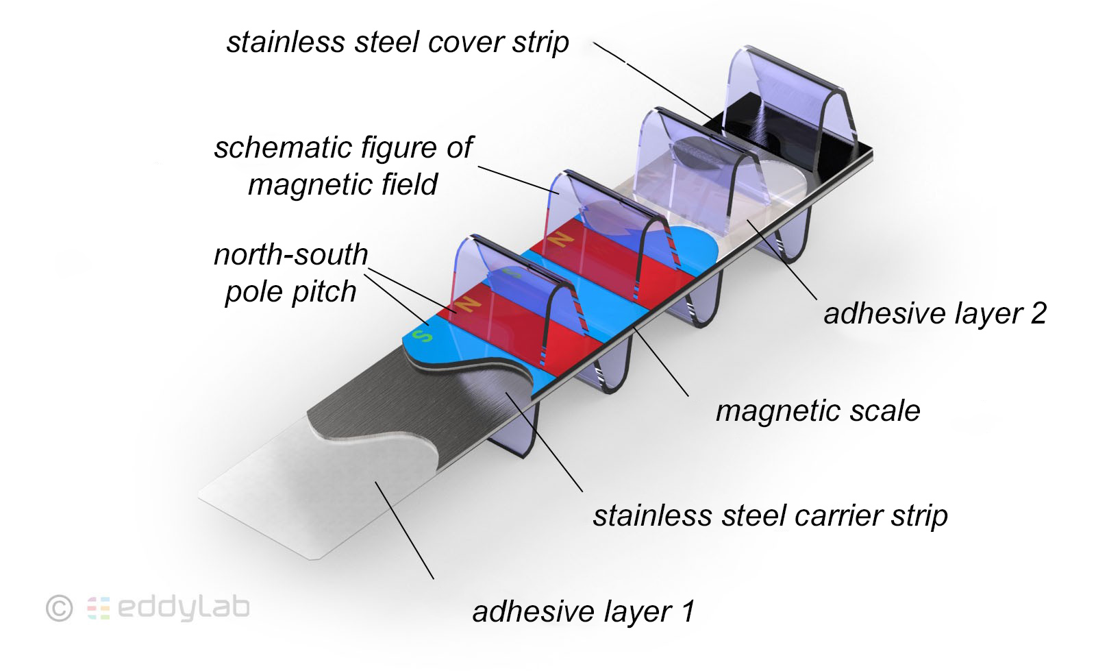 Structure of a flexible multipolar magnetic ruler
The Magnetic Ruler material was developed based on knowledge gained from hard disk and storage media production. It is characterized by an extremely high magnetic density and extreme resistance to external interference fields. Important magnetic characteristics of the material are, for example, the remanence Br with 0.2-0.25 T and the coercivity Hc with 120 kA/m. The flexible magnetic layer is covered with a protective layer and is also protected against damage by a stainless steel cover.
In addition to the Magnetic Ruler, the read head is required. This contains an array with the MR elements. The MR sensor is a thin-film sensor on a PCB. The generated output signal of the MR elements is related to the change in magnetic field strength (flux density) when the read head is moved across the magnetic pole pitch consisting of north and south poles. In this process, each individual MR sensor generates a sinusoidal signal in the pole passage. Harmonic oscillations that occur in addition to the sinusoidal signal are eliminated by a special arrangement of the MR elements in the array, so that the signal-to-noise ratio is extremely high for this sensor technology and the signal is free of harmonic oscillations.
By using a sensor array, amplitude, phase and offset errors can be eliminated particularly effectively. This process qualifies the Digital Magnetic Ruler based on the Magnescale principle for difficult and delicate applications under high vibration and shock loads. Breakage of the magnetic tape is impossible.
Due to the high signal quality of the magnetically generated sinusoidal signal, very high resolutions with the highest interpolation accuracy can nowadays be achieved in the Magnescale systems by interpolation in the subsequent electronics, which were previously reserved for optical systems such as glass scales.
The evaluation unit interpolates the sinusoidal signals to an incremental TTL output signal with specified resolution (transistor-transistor logic). With the help of the interpolator, the phase-shifted periods of the sinusoidal curves are amplified and mathematically subdivided and output as a robust pulse signal with the highest measurement resolution.
The TTL signal (transistor-transistor logic) requires a supply voltage of 5V or 24V (HTL). The pulses are output as high level and low level, where the high level corresponds to a voltage value close to the operating voltage and the low level is reproduced as a low voltage value (usually close to 0V).
To keep the level definition, a minimum output voltage is guaranteed for the high level on the output side and a minimum input voltage is required on the input side. With regard to the low level, a maximum output or input voltage is defined.
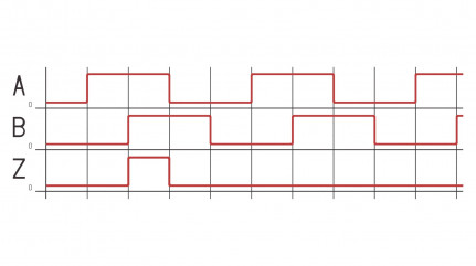 ABZ-pulse
The TTL output signal can be processed via various counter cards and thus be connected to all common controllers. The counter cards recognize the pulses of the TTL signal depending on the setting of the clock and the speed.
Reference points are suitable for setting the zero point of the measuring system. For this purpose, an additional magnetic signal track (Z track) is inserted in the magnetic tape. If the read head is on the reference point or passes over it, a separate reference signal is output. This technology is used after the machine has been started or if the system has previously been de-energized and no position information is available. In a reference run, the machine control moves the linearly moving part in a defined manner to its initial position. The reference point is traversed and the position or counter value is set to zero or to a defined start value. The reference run can be carried out as often as required or at sensible events such as machine start, after emergency stop actuation or for offset correction in the warm-up process of a machine.
Various Magnetic Rulers, such as the SL700 series, also have one or more reference points or multi-reference points.
SL110/SL130: no reference point
SL331: no reference point
SL700: no reference point
SL710: a single reference point (the position of the reference point can be selected and must be specified when ordering the system. The reference point accuracy here is +/- 1 mm.
SL720: (Multi-) reference points are placed recurrently every 60 mm on the magnetic tape as a separate track. However, the machine control cannot distinguish between the individual reference points. The system works incrementally. For this purpose, the position signal can be corrected at any point with a known position by passing over the reference point. This is ideal for correcting the temperature response of the machine or correcting different load conditions and for particularly high accuracy requirements.
SL730: Additional distance-coded reference marks are placed between constant successive reference points. Each reference mark is thus located between two reference points. The position of the reference mark between the two reference points corresponds to the absolute distance, so that the absolute position in the measuring range can be determined by evaluating the position of the reference mark between two reference points. This method requires an algorithm in the machine control system and offers the possibility of restoring the absolute position signal at any position by traversing two reference points with evaluation of the position of the reference mark between the reference points. Depending on the absolute position, the reference mark is shifted further by 800 µm between the reference points and indicates the absolute position in the measuring range. E.g. the absolute position of the 3rd reference mark at a distance of 80 mm between two reference points is: 3x80 mm + 3x800 µm.
This design is advantageous for particularly long travels such as portal milling machines or vertical machining centers up to 100 m linear travel, where a return of the drive to the starting position (usually a defined machine side or end position of the linear unit) would mean a disproportionately high effort.
All Magnescale Magnetic Rulers and Scales can be operated as "stand-alone", but also in combination with multifunctional displays or interface modules. This provides many quick and easy installation options. Likewise, Magnescale magnetic tapes can be connected to various third-party controllers or displays.
Magnescale also offers flexible multi-interfaces for the digital probes. A maximum of 64 magnetic tapes can be connected via an RS-232C interface, which is also optionally available with a BCD interface.
Both multi-function displays and the various interface modules can be used to record data via the PC.
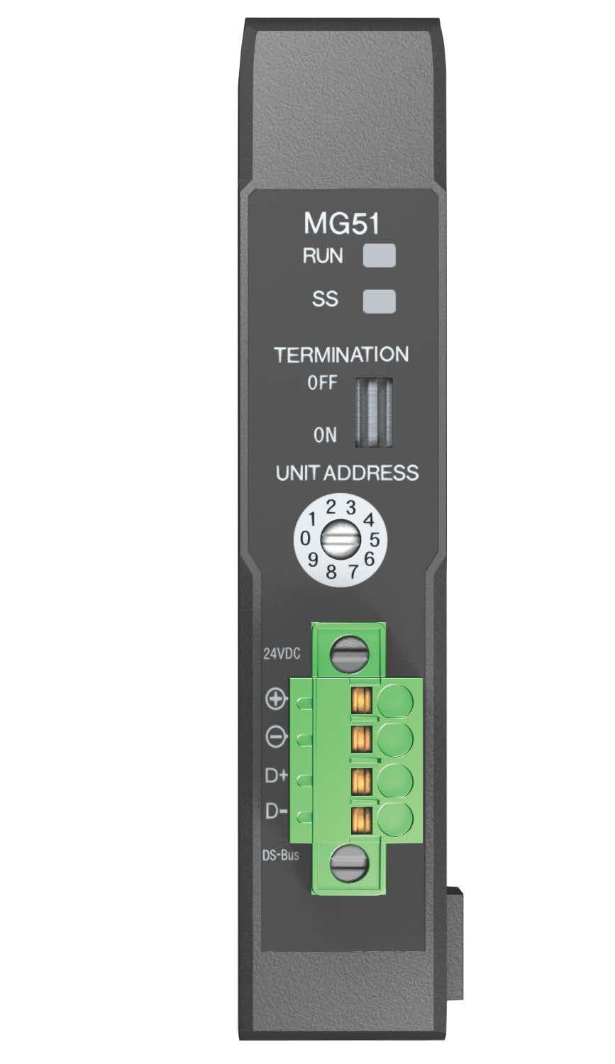
MG Interface
With an effective measuring range of up to 30,000 mm, all desired measuring ranges can be realized without sacrificing resolution.
Digital Magnetic Rulers and Scales can be used almost universally due to their various designs. The Magnescale measuring systems are mainly made of steel and therefore have the same thermal behavior as e.g. machine tools with cast iron bed. In contrast to optical measuring systems with aluminum housings, which are partly mounted floating, the Magnescale measuring systems are firmly screwed to the machine bed. This rigid mounting method provides first-class vibration and shock resistance of the measuring systems.
When the ambient temperature changes, the Magnescale linear encoders behave like the machine bed, i.e. the expansion of the linear encoders corresponds to that of the machine bed. As a result, temperature changes have hardly any influence on the accuracy of the machine.
The magnetic operating principle is extremely insensitive to contamination such as oil, water and dust, since magnetic fields cannot be deflected or influenced by these. Of course, solid particles, such as chips or aggressive cooling emulsions, should not get into the measuring system, as these can damage the measuring system.
Digital Magnetic Rulers and Scales have very good linearity. Depending on the measuring range, linearities of up to ±0.2 µm can be achieved. With a measuring range of 30,000 mm, a linearity of ±283 µm is achieved.
A highly accurate resolution of 0.2 µm is also achieved at a traverse speed of up to 384 m/min.
Digital Magnetic Rulers and Scales respond exclusively to axial displacements of the read head. The displacement transducers are insensitive to radial displacement or a movement of the measured object that is not one hundred percent rectilinear, and the output signal is not influenced. However, it should be noted that the read head must not exceed the maximum distance to the magnetic ruler.
All Digital Magnetic Rulers and Scales are maintenance-free. Due to a contactless measurement, there is no friction or wear.
Since the signal processing of digital displacement sensors is not determined by characteristic curves of the individual elements, but by numerical processing, digital transducers are not subject to disturbances such as noise or distortion.
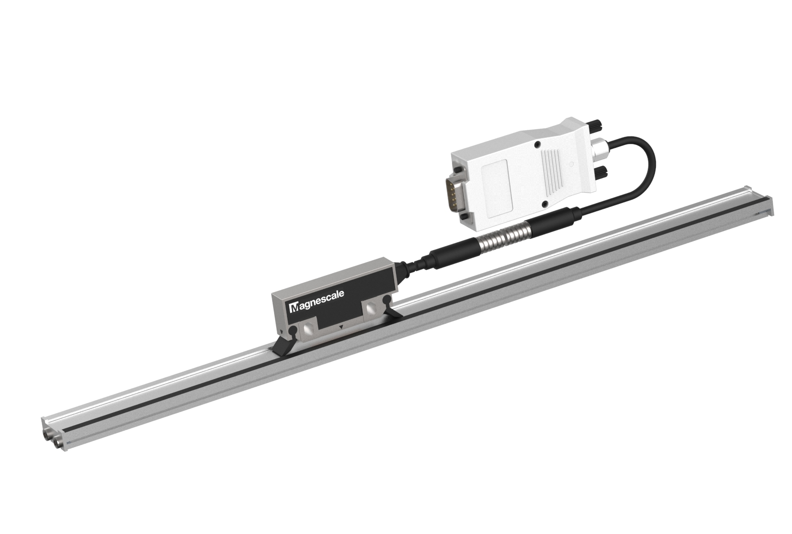 SL110/130 with PL20C
The PL81/82 read head can be used to select the output signal between TTL and open collector. Likewise, the resolution can be set. The magnetic tape is robust and easy to install.
SL331 with PL60 is a low-maintenance solution and quickly installed. It achieves a resolution of up to 2 µm. A TTL or HTL open collector signal is output via the MJ100 and MJ110 interpolators.
The SL700 series offers a high resolution of 0.2 µm. In addition, this variant can be ordered without, with one or more reference points and also reference marks. Depending on the PL101 version, the system outputs a 1V peak-to-peak or TTL signal. With a travel speed of up to 384 m/min, this system is ideally suited for dynamic measurements. It covers a measuring range of 50 mm - 100 m.